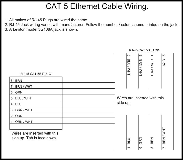
How to Wire a CAT5 Ethernet Cable
Back to Electronics Index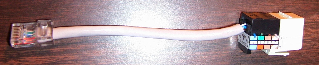
Traffic Light Ladder Logic With Allan Bradley SLC-500
Traffic Light Ladder Logic using only On-Timers and Off-TimersThis program was run on RSLogix Emulate.
A 5 second red light overlap is implemented to ensure the instersection is empty before a green light is lit.
Lights sequence as follows in seconds:
YEL North-South: 000-005, 060-065, 120-125
RED North-South: 005-035, 065-095, 125-155
GRN North-South: 040-060, 100-120
YEL East-West: 030-035, 090-095, 150-155
RED East-West: 000-010, 035-070, 095-130
GRN East-West: 010-030, 070-090, 130-150
Link to Youtube Video
Back to Electronics Index


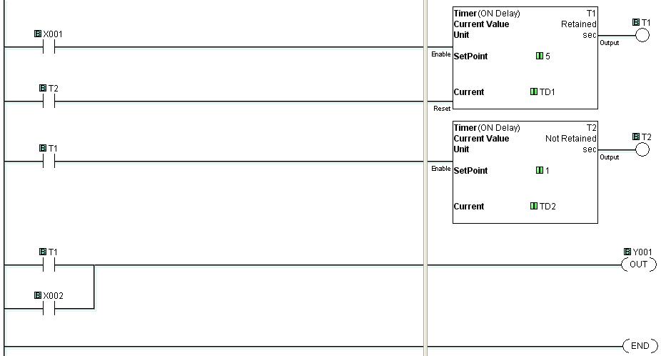
Start (with delay) - Stop Circuit using a ClickPLC C0-00AR-D from Automation Direct
This circuit was made to demonstarte how a delay can be added to the circuit without the need for any re-wiring. The top image shows the ladder logic and the bottom image shows the actual wiring.Delay to start = 5 seconds
Start delay time resets if finger is removed from start button before 5 seconds transpire
Link to Youtube Video
Back to Electronics Index
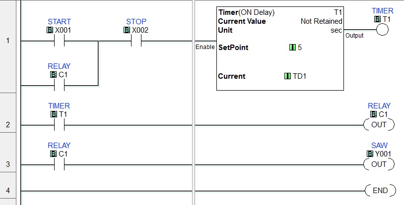

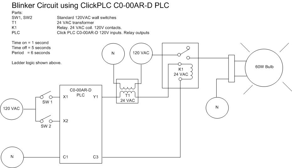
Clock Circuit using a ClickPLC C0-00AR-D from Automation Direct
This is my first test circuit.The top image shows the ladder logic and the bottom image shows the actual wiring.I could have omitted the transformer and used a 120 VAC coil relay but all my relays, contactors, etc are 24 VAC.
Period = 6 seconds
On time = 1 second
Off time = 5 seconds
Back to Electronics Index
Hartley Oscillator
My Post on sci electronics designMy problem is that when I read about locus root, it is all math and I don't know how to apply it to this simple circuit. When I read about hartley oscillators I usually see "freq = 1/(2*pi*sqrt(LC)) which is a little simplistic. ========================================7:45 AM 10/12/2009 Response from Roger Lascelles
The simulation program does non-linear analysis, so it does not work with equations you would use for root locus with small signal parameters. Instead, it tracks the movement of charge at small steps in time, at each step iterating to get a solution which satisfies the equations describing each circuit component, including the equations for the non-linear transistor. If it was linear analysis, you would only see sinewaves. Again, I recommend Wes Haywards "Introduction to RF Design. He will present you with equations, but also discusses the result you want to achieve. In the end, oscillator design means trading off many requirements, noise, amplitude, power, drift. It turns out that establishing that you have correct loop gain and phase is the easy part, at least below UHF. Haywood uses surprisingly simple transistor models which you will find give you a feel for the issues. He also has a Smith Chart design method for the higher frequencies. The book has a bit of everything, and will get you going in the RF world. If you want to, draw the hybrid pi model of the transistor, add the other components, then break the loop and calculate gain and phase around the loop. You will find this analysis in plenty of Uni library textbooks. It is useless for designing good oscillators at the 3 or 4 MHz where your oscillator functions, because those equations only tell you that the oscillator will start, and nothing about its performance. Feedback phase does not have to be perfectly 180 degrees at resonance, because oscillation can still occur at a frequency somewhat away from resonance, where the tuned circuit gives enough phase shift to give make up the exact 180 degrees. This is why oscillators like yours mostly work, and why the linear ?will it start? analysis is not much help. Your oscillator is not a linear device, once it gets started. The transistor puts spikes of current into the tank circuit and nothing the rest of the time. Reduce DC current until you are free of clipping and you will have a decent oscillator. Apart from avoiding clipping, the other issue is the impedance presented by the tuned circuit to the transistor base and collector. A lower impedance presented to the collector lets you run at a higher collector current, storing more energy in the tank circuit and swamping thermal and transistor noise. A lower impedance presented to the base is associated with less feedback, so it can't be too low, but lower means the base loads the tuned circuit less and allows higher Q, giving a cleaner sinewave. L1 and L2 are mutually coupled in a Harley circuit, and since L1=L2 in your circuit, there is very heavy feedback, meaning your oscillator can't fail to work. So reduce L1 and increase L2 until it stops oscillating, then back off. Then bypass R5 with a capacitor and increase R5 until clipping stops. Roger
Back to Electronics Index
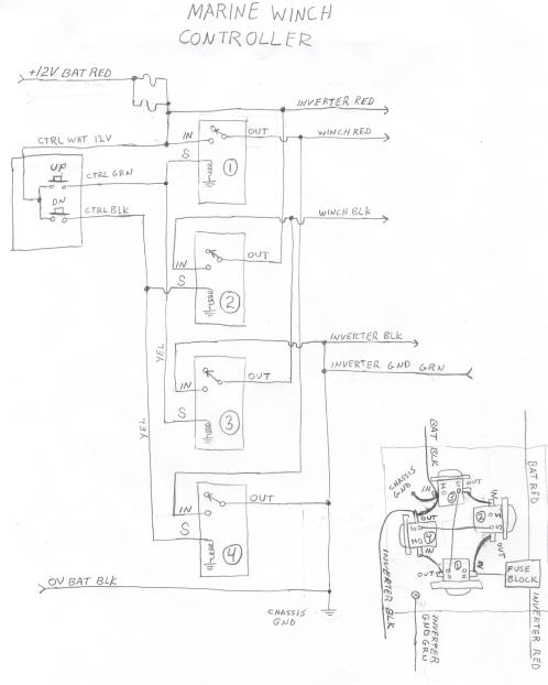
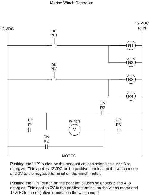
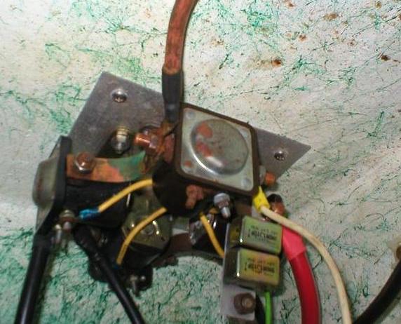
Winch controller used on a sea urchin boat
Warning, pressing the up and down buttons at the same time will cause a direct short between 12VDC and Ground.Theory of Operation
1. Pushing the "UP" button on the pendant causes solenoids 1 and 3 to energize. This puts the "WINCH RED" line at 12V and the "WINCH BLK" line at 0V. This causes the winch motor to rotate forwards.
2. Pushing the "DN" button on the pendant causes solenoids 2 and 4 to energize. This puts 0V on the "WINCH RED" line and 12V on the "WINCH BLK" line. This causes the winch motor to rotate backwards. Back to Electronics Index
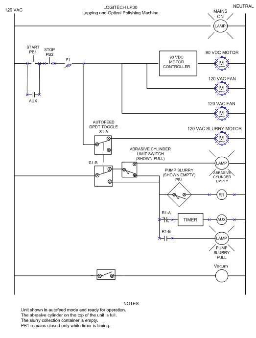
Logitech LP30 Polishing Machine
Theory of Operation1. Unit shown in autofeed mode and ready for operation
2. The abrasive cylinder on the top of the unit is full.
3. The slurry collection container on the bottom of the unit is empty.
4. The second rung is energized only while the timer is timing.
Back to Electronics Index
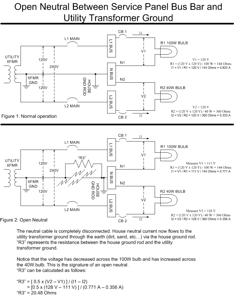
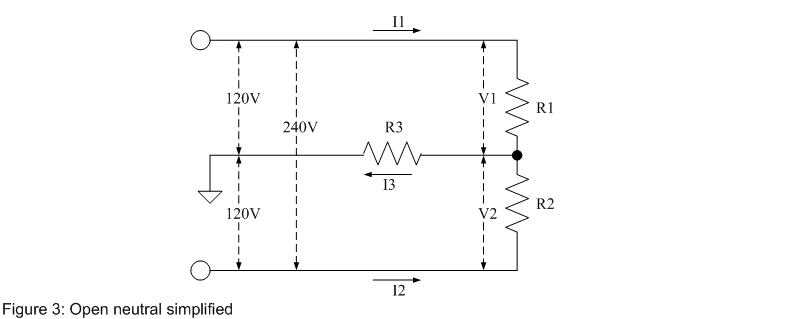
Open Neutral Between Service Panel Bus Bar and Utility Transformer Ground
Lights dim. Low power appliances blow.Back to Electronics Index
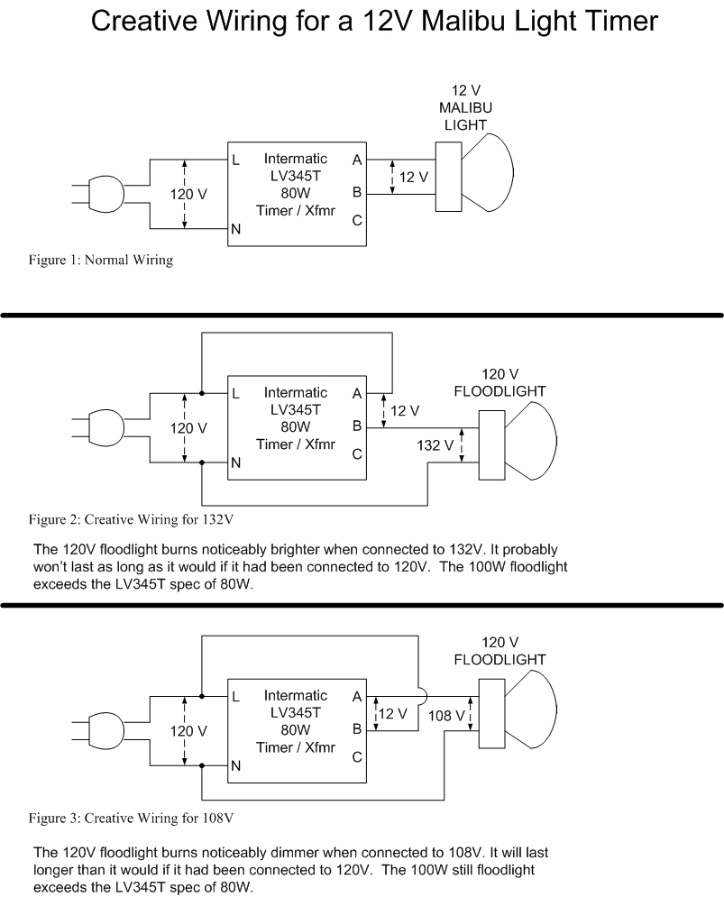
"Creative" Wiring used to Control a 120V Floodlight with a 12V Transformer
Violates NEC and UL. I encounted the 132V wiring at a customer site. It would have been a lot less expensive to use a simple lamp timer but you have to admit that it is interesting.Back to Electronics Index
"3-Way Switch Wiring
Nothing exotic about this. Just wanted it handyBack to Electronics Index

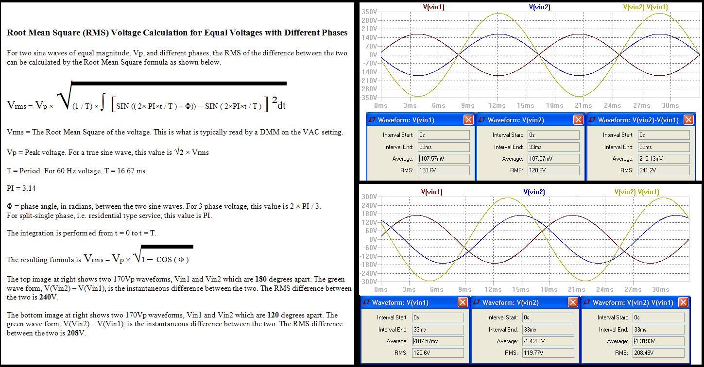
Phun with Fazes
240V or 208V Dependends on Phasing of 120VSee write up and images to right.
Back to Electronics Index
Homopolar Motor
Saw this on Youtube and had to make one.The force on the wire is described by the Lorentz Equation:
F = I L X B
Back to Electronics Index
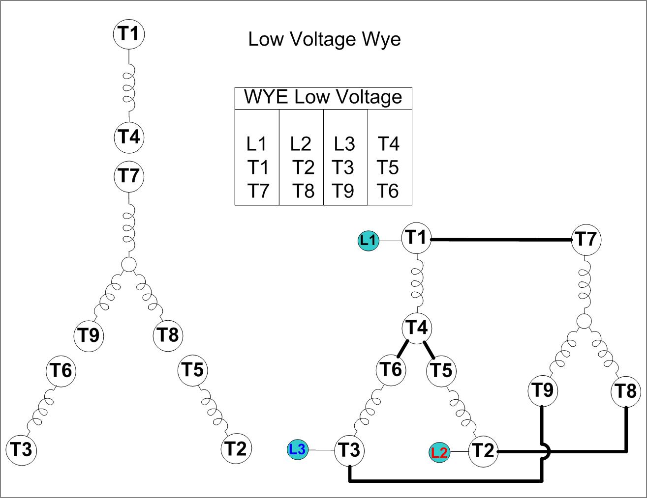
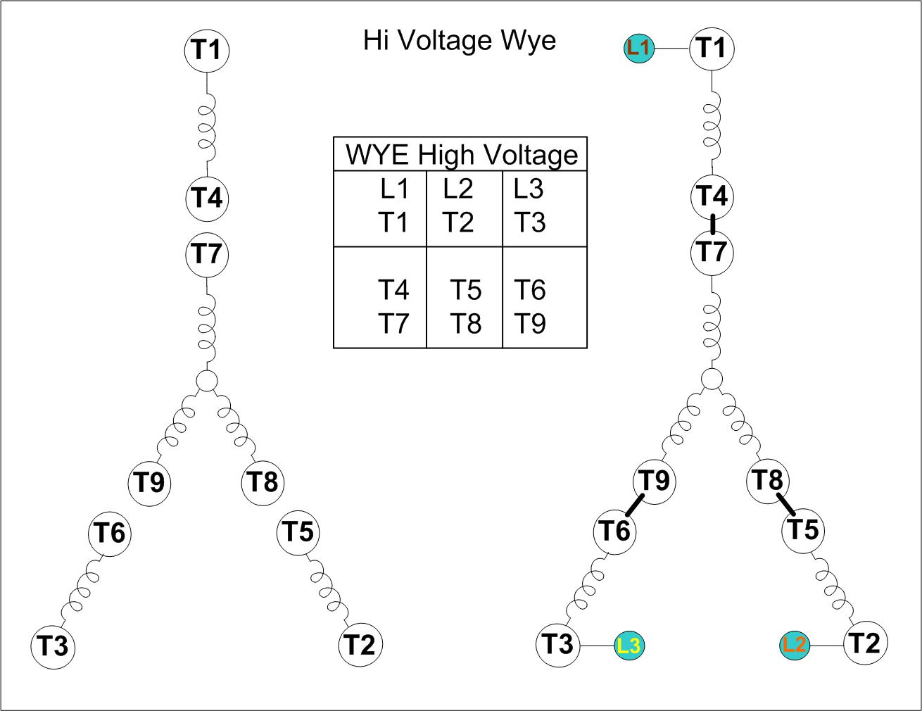
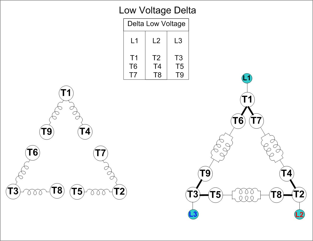
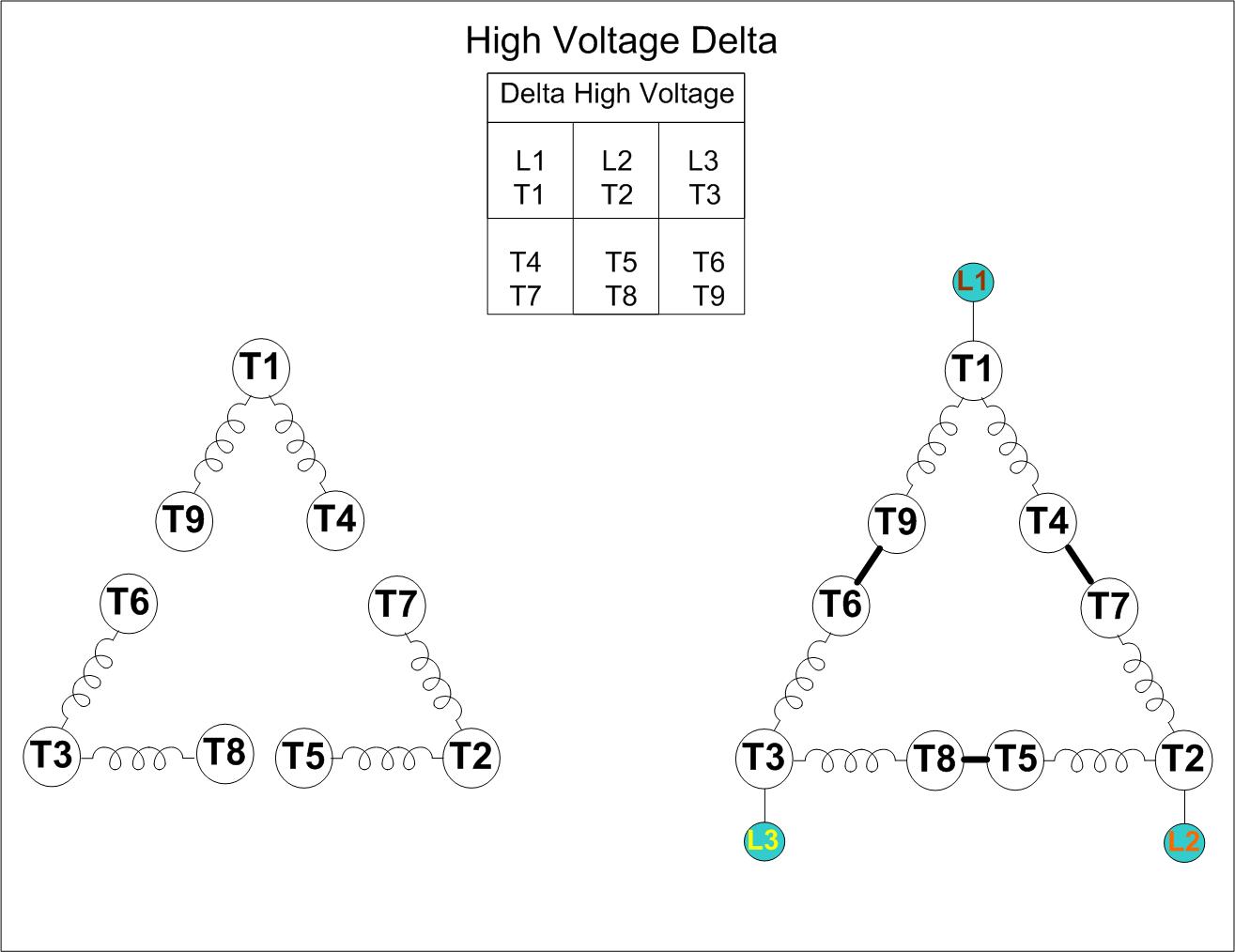
3-Phase Motor Strapping
Motor Strapping For...1. Low Voltage Wye 2. High Voltage Wye,
3. Low Voltage Delta, 4. High Voltage Delta
Back to Electronics Index